
Pressure Indicator Pid Symbol
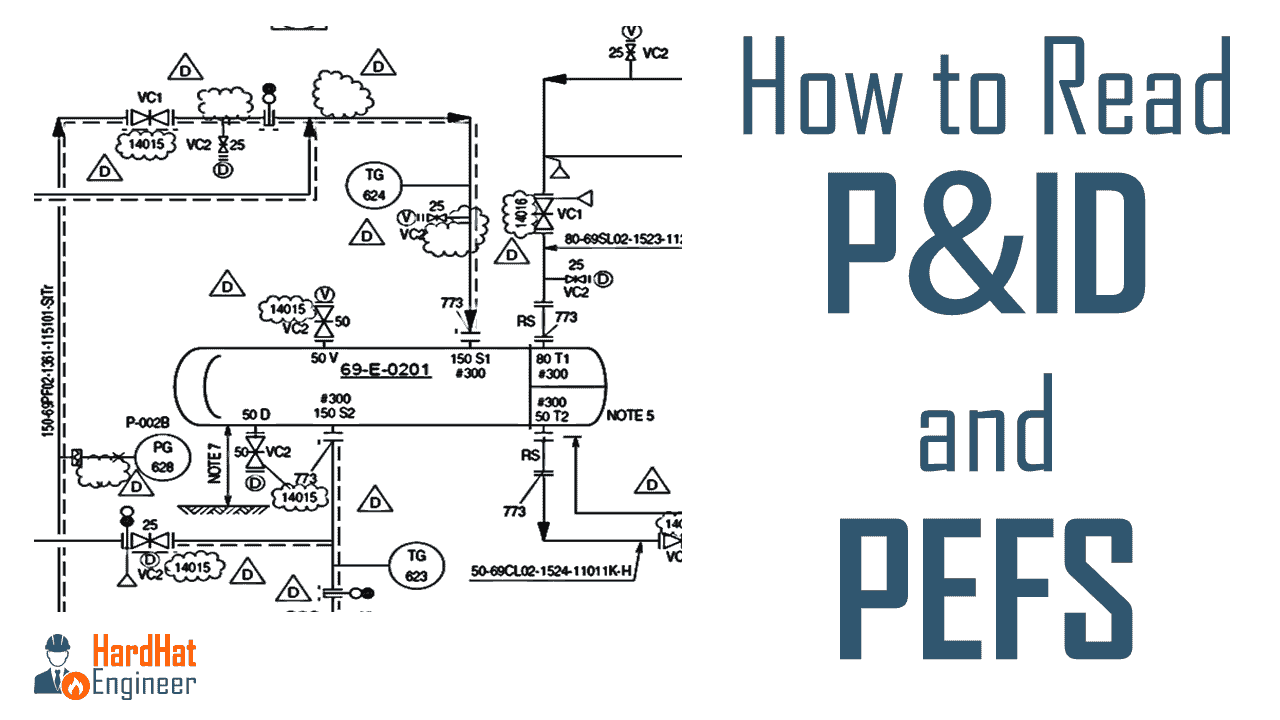
P&ID is an abbreviation meaning ‘ Piping and Instrumentation Diagram ‘ Piping and Instrumentation Diagrams are graphical representations of a process system These are fundamental to every standardized engineering project These twodimensional diagrams function as a blueprint for the engineering system’s design.
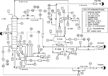
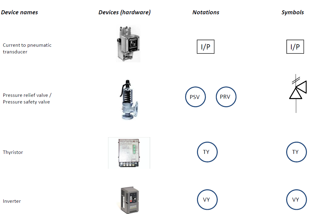
Pressure indicator pid symbol. P&ID symbols and notations One area of P&IDs that is standardized are the instrumentation symbols, the key to being able to understand P&IDs Instrumentation symbols appearing on diagrams adhere to ANSI/ISA’s S (R 1992) standards. Common "local" pressurerelated instruments include Pressure Indicators (PI), Pressure Transmitters and Delta Pressure Transmitters (PT), Pressure Controllers (PC), Pressure Safety Valves (PSV), Pressure Alarms High and Low (PAH and PAL) Take another look at the carbon filter P&ID excerpt and verify the following statements to be accurate. Legend & Symbols P&ID Bambang HN Tripatra, 1 Sept 14 Legend & Symbol Abbreviation Meaning BDV Indicator Flow Switch Non Intrusive Element Restricted Orifice Orifice Plate with Quick Change Fitting Low Pressure Process (300# ASME and lower) 1000 100 High Pressure Process (600# and higher) 00 0.
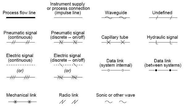
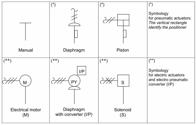
– ASME Boiler and Pressure Vessel Code Section VIII – Pressure Vessels • The Instrumentation, Systems, and Automation Society (ISA) – ISA 51 – Instrumentation Symbols and Identification – ISA 52 – Binary Logic Diagrams for Process Operations – ISA 53 – Graphic Symbols for Distributed Control / Shared Display. PIPING AND INSTRUMENTATION DIAGRAM P&ID 1 Pendahuluan 21 Line Instrument Symbol Berdasarkan line simbol ini dapat dibedakan sistem instrumentasi yang terpasang apakah pneumatic, electric atau hidrolic Berikut ini beberapa Local pressure indicator and pressure indicating transmitter with. Piping and Instrument Diagram (p&Id) Standard Symbols Detailed Documentation Free download as PDF File (pdf), Text File (txt) or read online for free.
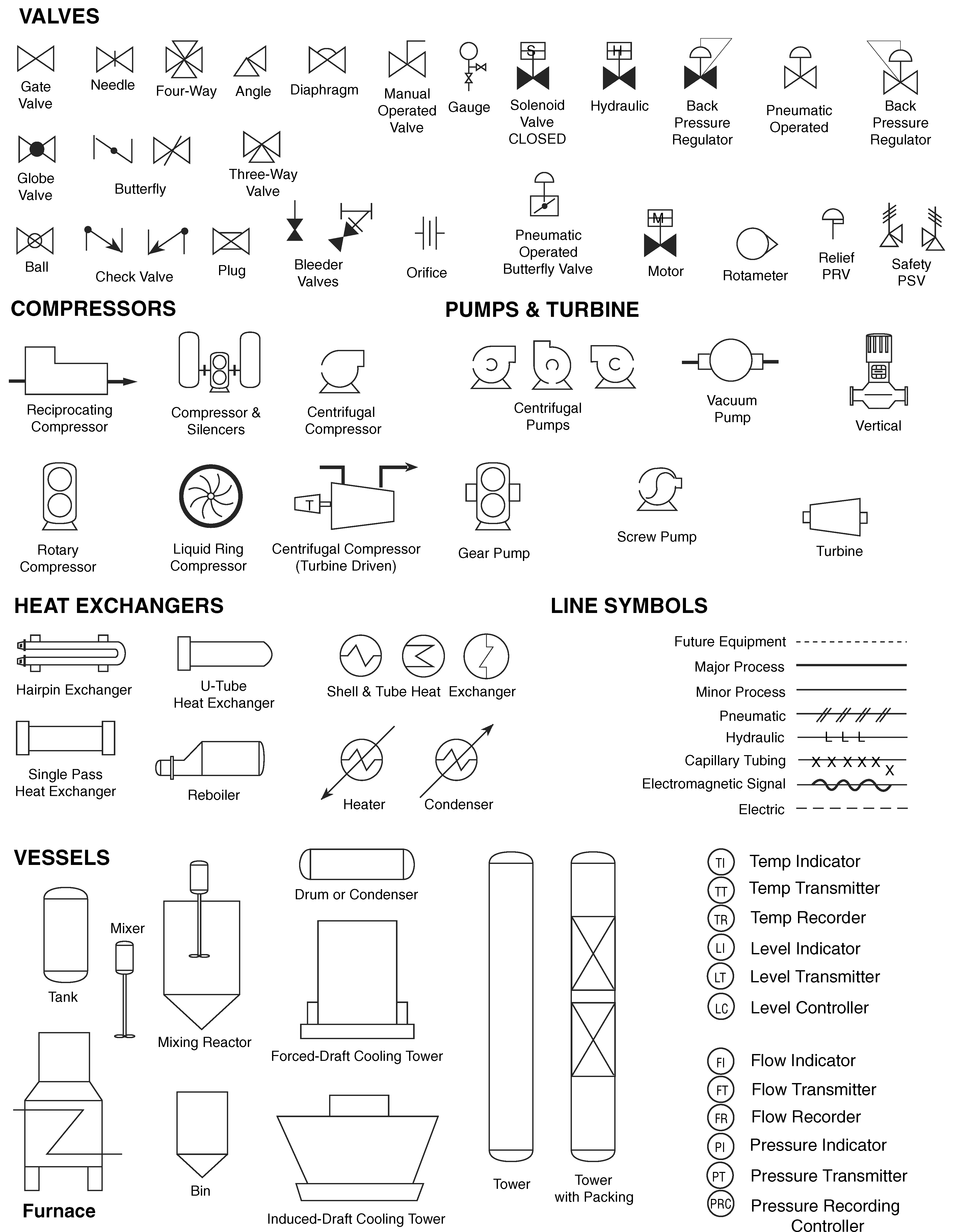
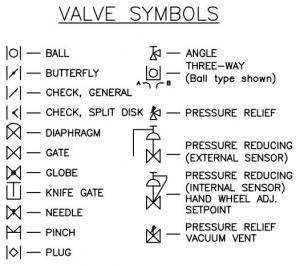
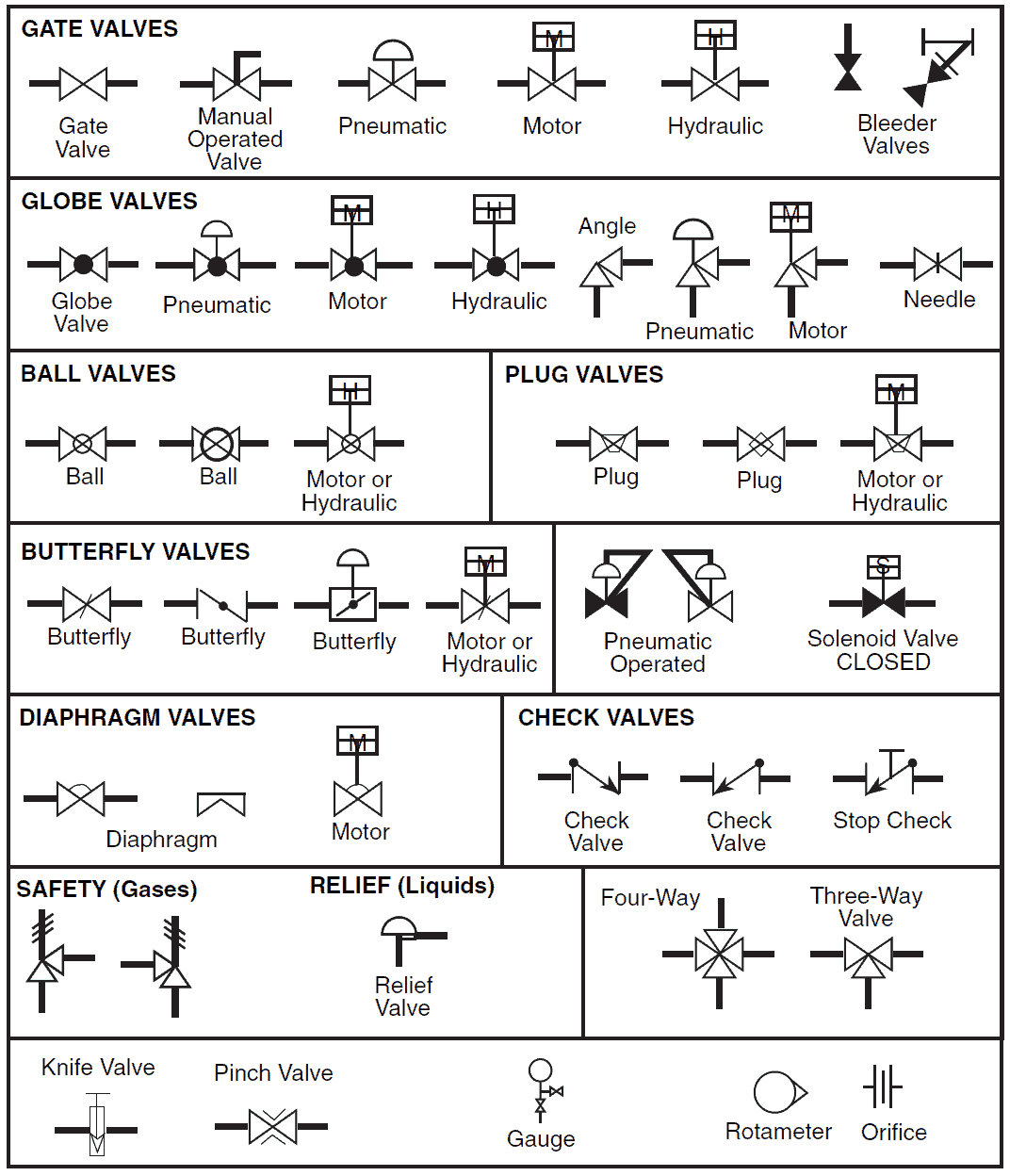
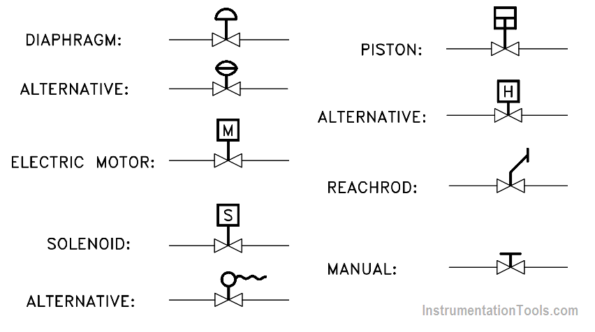
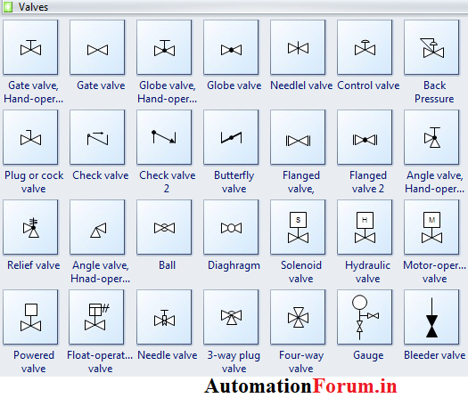
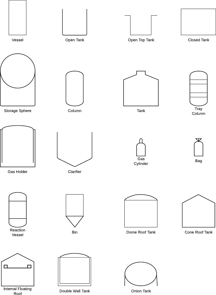
About P&ID symbols Piping and Instrumentation Diagram Standard Symbols Detailed Documentation provides a standard set of shapes & symbols for documenting P&ID and PFD, including standard shapes for instrument, valves, pump, heating exchanges, mixers, crushers, vessels, compressors, filters, motors and connecting shapes. Loop Diagram Symbols and P&IDs This P&ID diagram illustrates the use of software data links between controllers These controllers communicate over a communications bus and pass variables back and forth between the IOP (input output processor) sections of the DCS The communications processor will then put the information in. In this article, you are going to learn about different types of valve symbols used in P&ID Many types of valves are used in process piping and each has a different symbol This makes the valve one of the tricky parts of reading P&ID But with practice, you can easily remember these symbols and can read P&ID effectively.
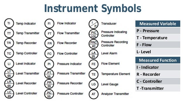
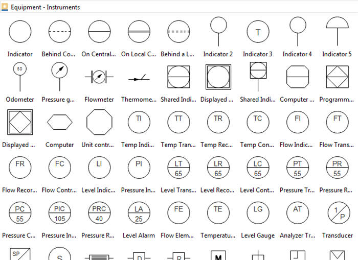
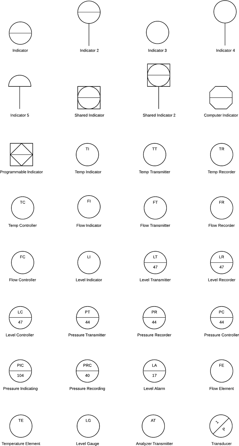
Instrumentation is a brain behind process control It senses, records and controls various process parameters to achieve best product quality at maximum economy and safety Here is a list of PID symbols pertaining to Instrumentation. About P&ID symbols Piping and instrumentation diagrams , or P&IDs, are used to create important documentation for process industry facilities The shapes in this legend are representative of the functional relationship between piping, instrumentation, and system equipment units. Loop Diagram Symbols and P&IDs This P&ID diagram illustrates the use of software data links between controllers These controllers communicate over a communications bus and pass variables back and forth between the IOP (input output processor) sections of the DCS The communications processor will then put the information in.
PFD symbols May change from company to company BS 5070, ISO and ISA S51 12. The piping and instrumentation diagram (P&ID), also known as mechanical flow diagram (MFD), provides information needed by engineers to begin planning for the construction of the plant The P&ID includes every mechanical aspect of the plant except the information given in Table 18. FC for Fail Closed;.
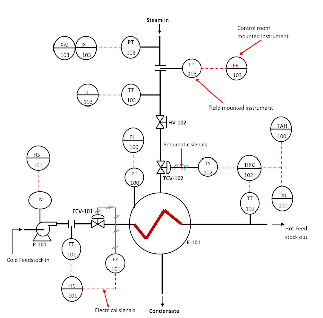
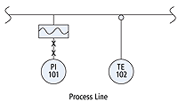
The wavy line inside the symbol for the diaphragm seal for PI101 should not be confused with the P&ID interconnection symbols for electromagnetic signals The correct answer is B, temperature sensor TE102 is inserted into a thermowell, and pressure indicator PI101 uses a filled capillary system and diaphragm seal to isolate it from the. P075 back pressure regulator self contained P127 double basket strainer P178evaporative air cooler P028flow indicator for P016 P076 back pressure regulator w/external tap P128 hose reel P179 opposing blade damper P029instruments common housing P077 pressure reducing regulator w/integral outlet pressure relief. On the developed P&ID, PT 103 is the pressure transmitter that measures the gas vessel pressure and sends the signal (electrical) to PIC 103, a pressure indicator and controller to indicate the measured pressure and at the same time send a command pneumatic signal depending on its set point to actuate the pressure control valve, PCV 103.
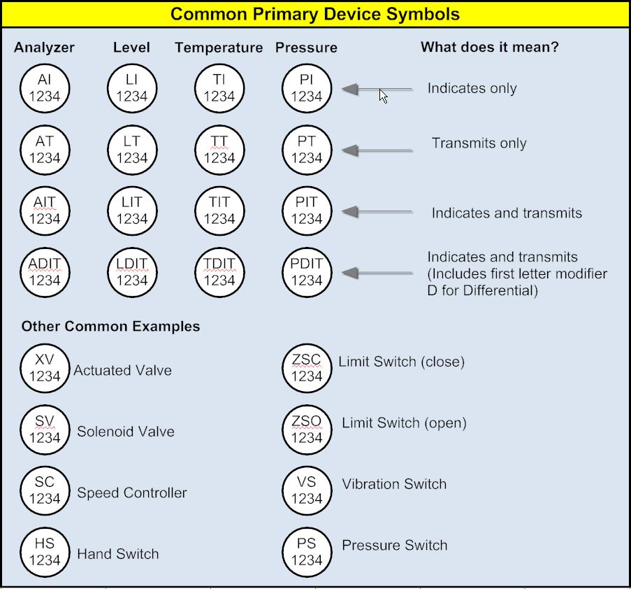
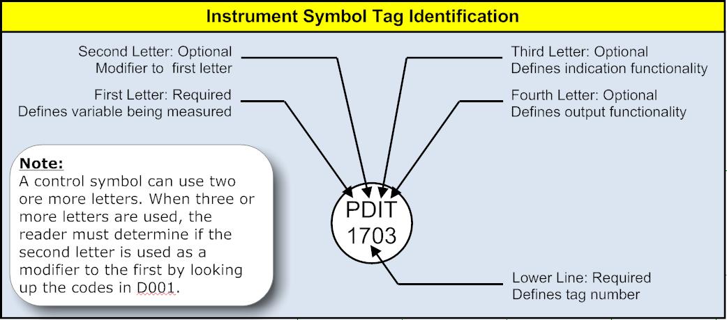
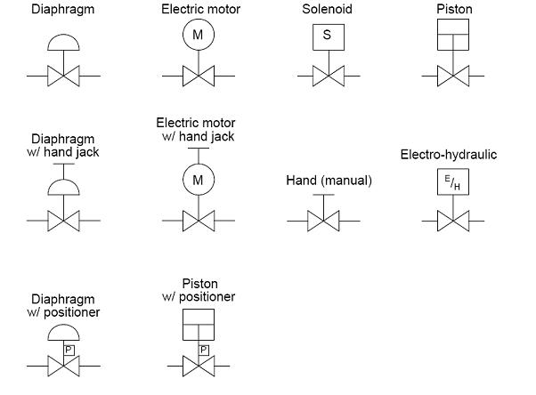
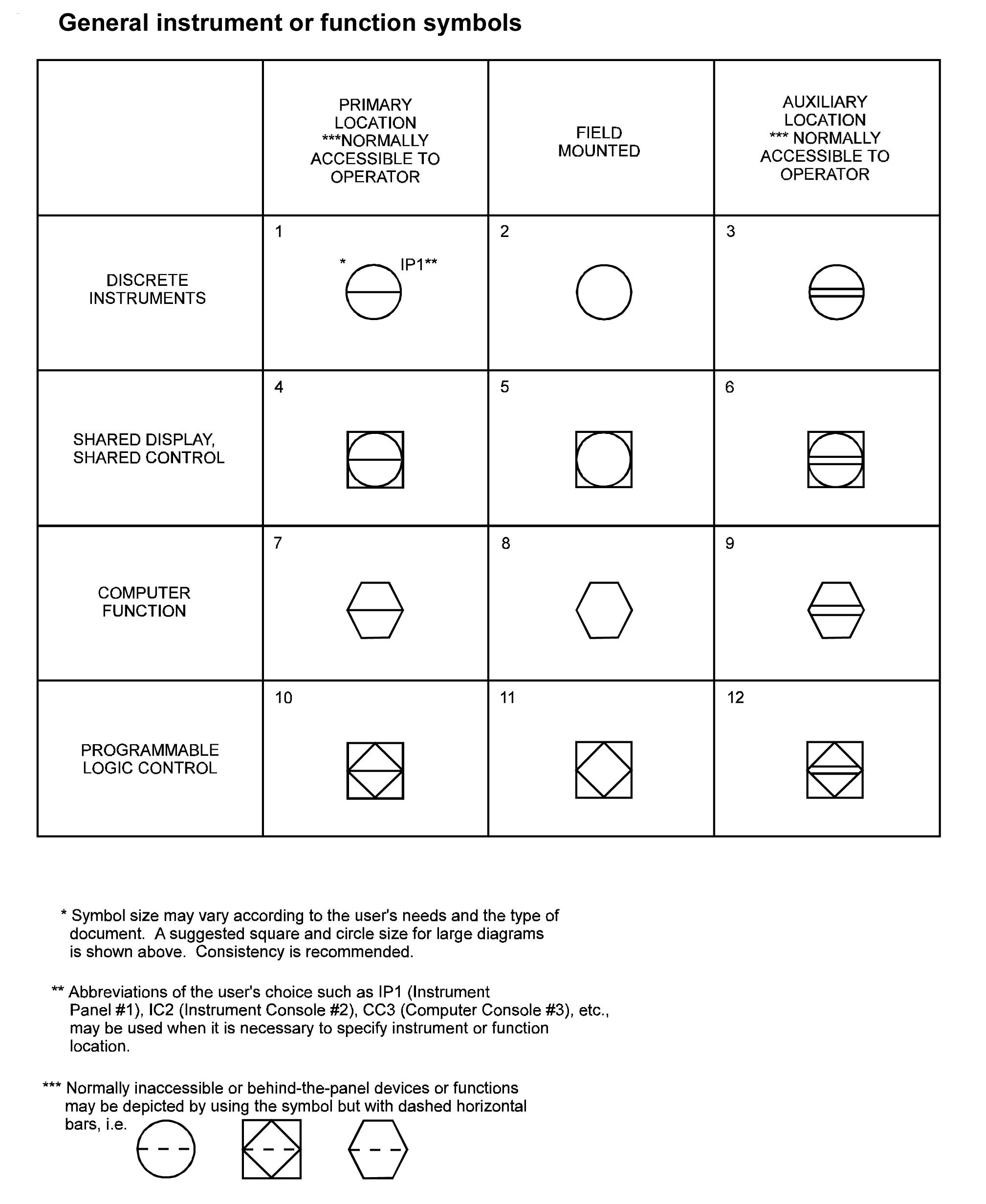
Gineering department has automated the unit Pressure, temperature, flow, and level control loops are all included on the unit P&ID Basic Instrument Symbols Process technicians use P&IDs to identify all of the equipment, instru ments, and piping found in their units New technicians use these drawings. Typically instrument abbreviations consist of two parts The first letter indicates the process The second letter or two letters indicates the function. (9)Actuator symbols and 21, when combined with element symbol 2, represent pressure safety valves(10)The symbols are applicable to all types of control valves and actuators535 Table 55 Functional diagramming symbols(1) Signal flow is assumed to be from toptobottom or from lefttoright(2) Symbols are shown in a vertical diagram.
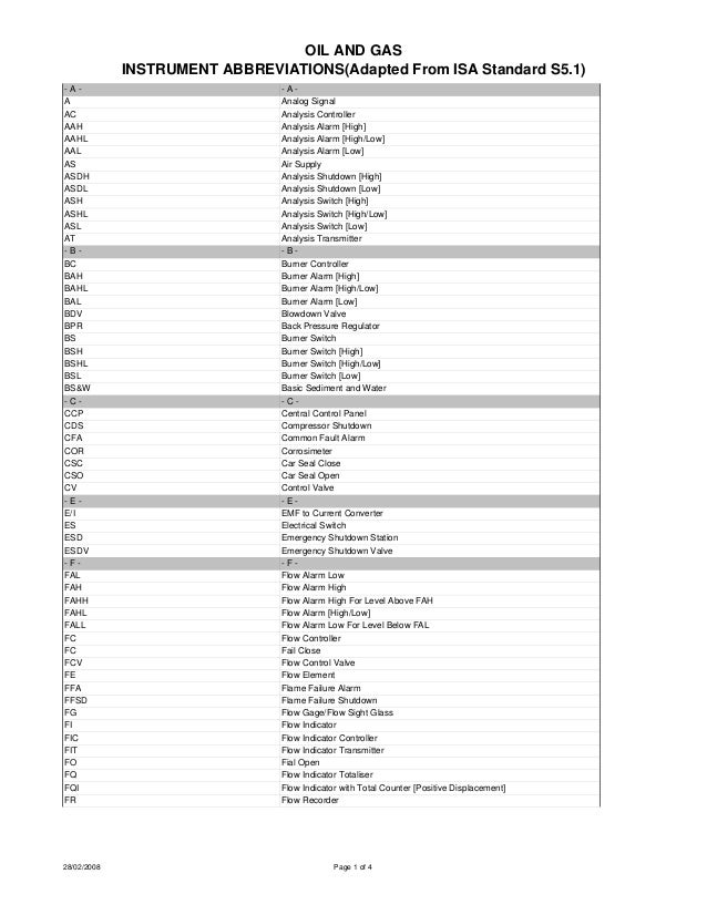
The instrumentation Abbreviations table used in P&ID, the table below contains some of the instrument abbreviations,(Adapted From ISA Standard S5). Piping and Instrument Diagram Standard Symbols Detailed Documentation provides a standard set of shapes & symbols for documenting P&ID and PFD, including standard shapes of instrument, valves, pump, heating exchanges, mixers, crushers, vessels, compressors, filters, motors and connecting shapes. The fail positions may be identified on the P&ID using letters below the valve symbol FO for Fail Open;.
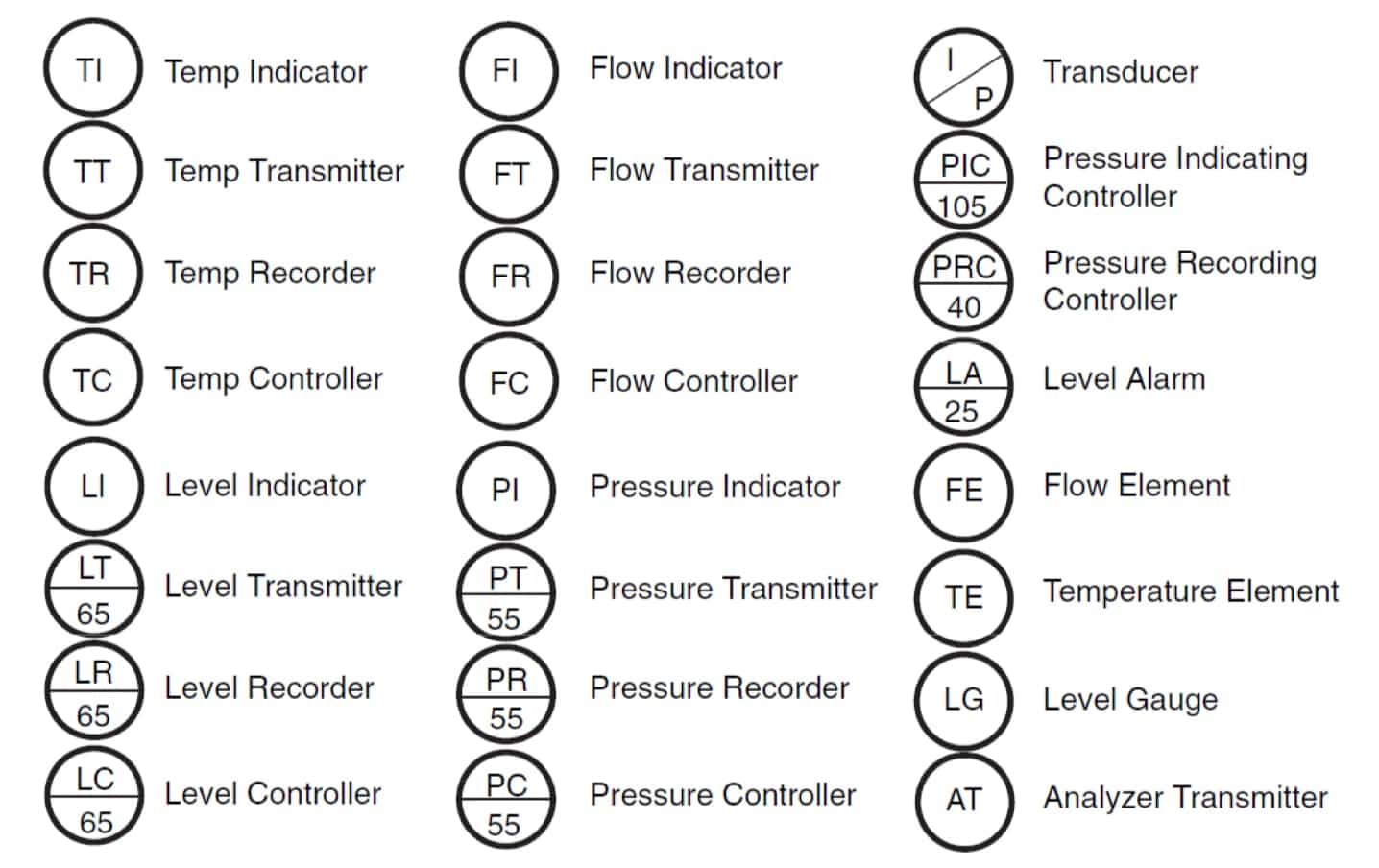
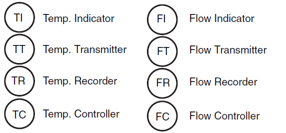
FL for Fail Last or Locked Pressure Loop Level Loop Flow Loop P & ID Symbology & Abbreviation Valve type. Example ISA symbols for a Level Indicator A level indicator will receive the symbol "L" for the process variable "Level", and "I" for the "Indicator" type of instrument Both combines to. ForcedDraft Cooling Tower Flow Indicator Flow Transmitter Flow Recorder Pressure Indicator Pressure Transmitter Pressure Recording Controller FI FT FR PI PT PRC Temp Indicator Temp Transmitter Temp Recorder Level Indicator Level Transmitter Level Controller TI TT TR LI LT LC Figure 121a Process and Instrument Symbols _12_ch12_p.
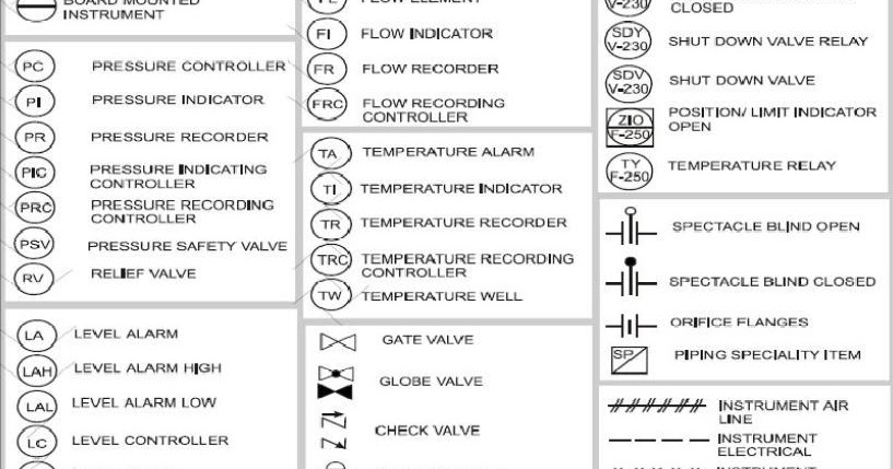
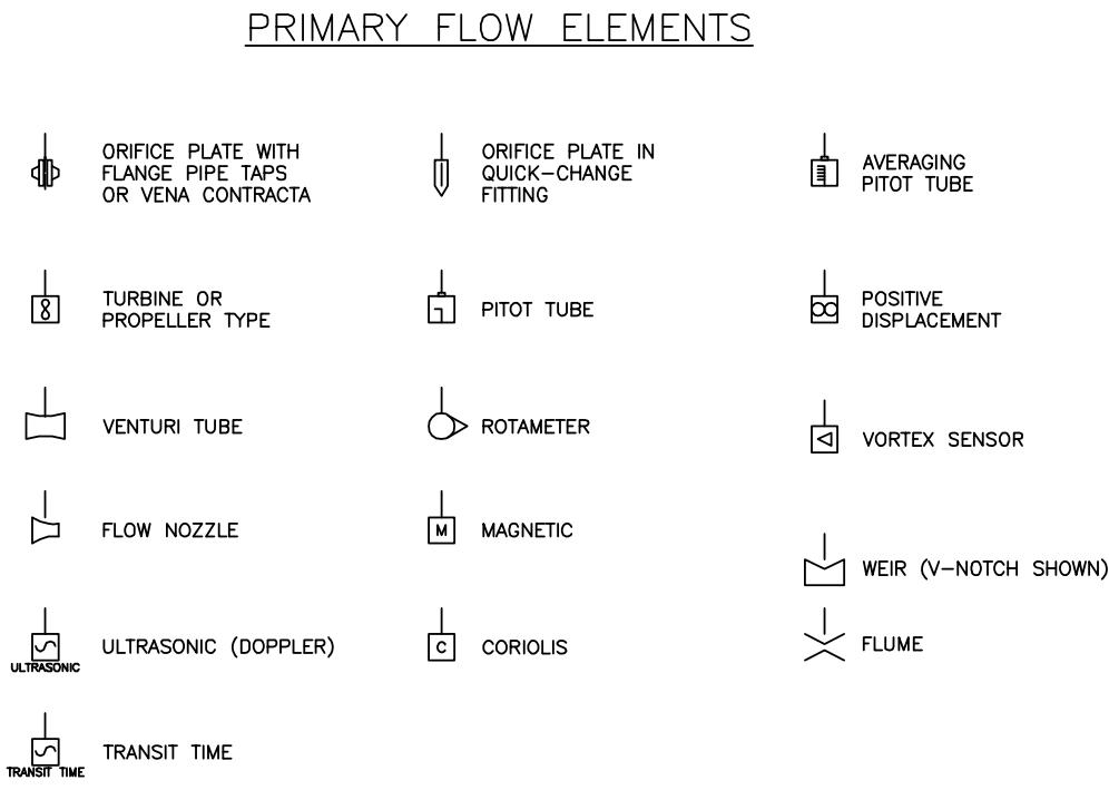
Start studying P/ID Instruments Learn vocabulary, terms, and more with flashcards, games, and other study tools. P&idabbreviation 1 OIL AND GAS INSTRUMENT ABBREVIATIONS(Adapted From ISA Standard S51) A A A Analog Signal AC Analysis Controller AAH Analysis Alarm High AAHL Analysis Alarm High/Low AAL Analysis Alarm Low AS Air Supply ASDH Analysis Shutdown High ASDL Analysis Shutdown Low ASH Analysis Switch High ASHL Analysis Switch High/Low ASL Analysis Switch Low AT Analysis. P&ID GENERAL SYMBOLOGY 1/5 P&ID GENERAL SYMBOLOGY 2/5 P&ID GENERAL SYMBOLOGY 3/5 PDI Differential Pressure Indicator PI Pressure Indicator F Filter FI Flow Indicator FEFlow Element FTFlow Transmitter FLOW ELEMENT SYMBOLS ORIFICE UNION VENTURI METER AVERAGING PITOT (ANNUBAR) VALVE AND CONTROL VALVE.
You can find all the predesigned P&ID symbols under the Industrial Automation and PID category, which will be used for representing the functional relationships between piping, instrumentation, and system equipment units Look at the video below to know how to use P&ID symbols and make a P&ID with EdrawMax. Details about the P&ID symbols Each symbol is drawn to 11 scale on layer zero with “bylayer” attributes Once inserted, simply rotate the symbol into position and it will take on the characteristics of your current layer settings Valve and instrument symbols also contain builtin attributes. Piping and Instrumentation Diagram (P&ID) Piping and Instrumentation Diagram (P&ID) is a drawing elaborating the details of piping and instrumentation of a processing plant, developed at the design stage P&ID is later used for assistance for construction of the corresponding plant and for operating that plant.
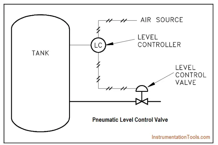
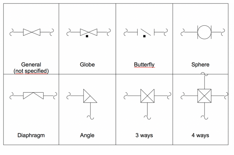
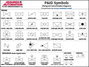
Most P&ID diagrams will then have a symbol with an arrow labeled for another specific piece of machinery in the facility or it may simply say to Process This will indicate that if you need to trace the system further, you will need the diagrams for that specific equipment Hopefully by now you are getting a feel for following a P&ID diagram. Valve Symbols for P&IDs The generic symbol for a 2way valve is two triangles pointing to each other with the tips of the inner points touching The pipe lines are represented by lines connecting to each side of the valve symbol Various types of lines are used to represent different pipes, tubes, and hoses. P&ID GENERAL SYMBOLOGY 1/5 P&ID GENERAL SYMBOLOGY 2/5 P&ID GENERAL SYMBOLOGY 3/5 PDI Differential Pressure Indicator PI Pressure Indicator F Filter FI Flow Indicator FEFlow Element FTFlow Transmitter FLOW ELEMENT SYMBOLS ORIFICE UNION VENTURI METER AVERAGING PITOT (ANNUBAR) VALVE AND CONTROL VALVE.
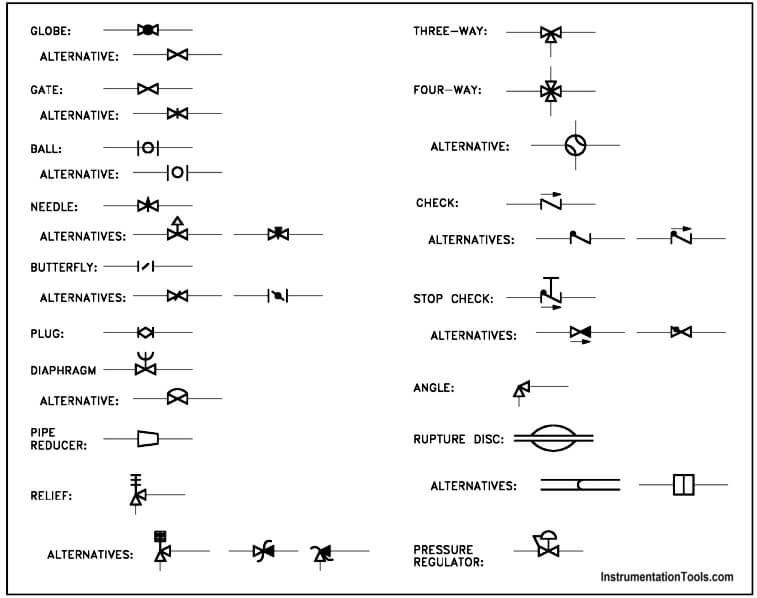
P&ID و PFD يتعنص يناوخ هشقن Pressure Indicator Pressure Transmitter Pressure Recorder Pressure Controller INSTRUMENT LOCATION The presence or absence of a line determines the location of Symbol size may vary according to the user's needs and the tyl'e of document 2 Abbreviations of the user's choice may be used when. In this article, you are going to learn about different types of valve symbols used in P&ID Many types of valves are used in process piping and each has a different symbol This makes the valve one of the tricky parts of reading P&ID But with practice, you can easily remember these symbols and can read P&ID effectively. The instrumentation Abbreviations table used in P&ID, the table below contains some of the instrument abbreviations,(Adapted From ISA Standard S5).
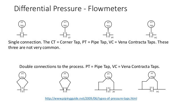
The instrumentation Abbreviations table used in P&ID, the table below contains some of the instrument abbreviations,(Adapted From ISA Standard S5). Module 2 Engineering Fluid Diagrams and Prints vi ENABLING OBJECTIVES (cont) 15 IDENTIFY the symbols used on engineering P&IDs for the following basic types of instrumentation a Differential pressure cell b Temperature element. P&ID GENERAL SYMBOLOGY 1/5 P&ID GENERAL SYMBOLOGY 2/5 P&ID GENERAL SYMBOLOGY 3/5 PDI Differential Pressure Indicator PI Pressure Indicator F Filter FI Flow Indicator FEFlow Element FTFlow Transmitter FLOW ELEMENT SYMBOLS ORIFICE UNION VENTURI METER AVERAGING PITOT (ANNUBAR) VALVE AND CONTROL VALVE.
The last switch is a LSHH which turns on an indicator light on a pump panel and also sends a signal to an autodialer We currently show the LSL and LSH that turns the pump on or off with an LSL bubble that has a dashed line going to one side of the motor with the word "OFF" and an LSH bubble that has a dashed line going to other side of the. Within the symbol, indicates that the component is pressure compensated 211 A line terminating in a dot to represent a thermometer is the symbol for temperature cause or effect See Temperature Controls 79 Temperature indicators and. Create P&ID Symbols in AutoCAD P&ID or AutoCAD Plant 3D http//wwwautodeskcom/autocadplant3d.
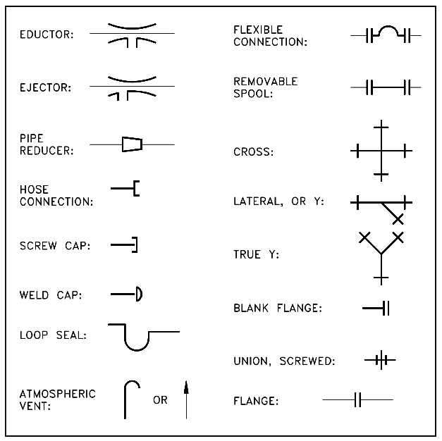
As per p&id ia safety interlock note 2 (where applicable) vent note 4 note 1, 3 coriolis flow meter urs energy & construction inc an aecom company 1 loop numbers for tags are taken from the valve tag, as shown on each p&id that references this detail 2 interlock number and proper symbol (dcs or plc) will be shown on process p&id 3. The symbols used in piping and Instrumentation diagrams or drawings are many and varied I have dealt with some of these symbols before but here I have given a comprehensive list of the common P&ID symbols of process equipment such as valves, flowmeters, piping line connections, and much more. The piping and instrumentation diagram (P&ID), also known as mechanical flow diagram (MFD), provides information needed by engineers to begin planning for the construction of the plant The P&ID includes every mechanical aspect of the plant except the information given in Table 18.
P&ID Diagram Online Drawing Tool ;. P&ID is the acronym for “Piping and instrumentation diagram”, ie a very detailed diagram showing the processes happening within a plant, the involved equipment, and their interconnections A set of standardized P&ID symbols is used by process engineers to draft such diagrams. Instrumentation is a brain behind process control It senses, records and controls various process parameters to achieve best product quality at maximum economy and safety Here is a list of PID symbols pertaining to Instrumentation.
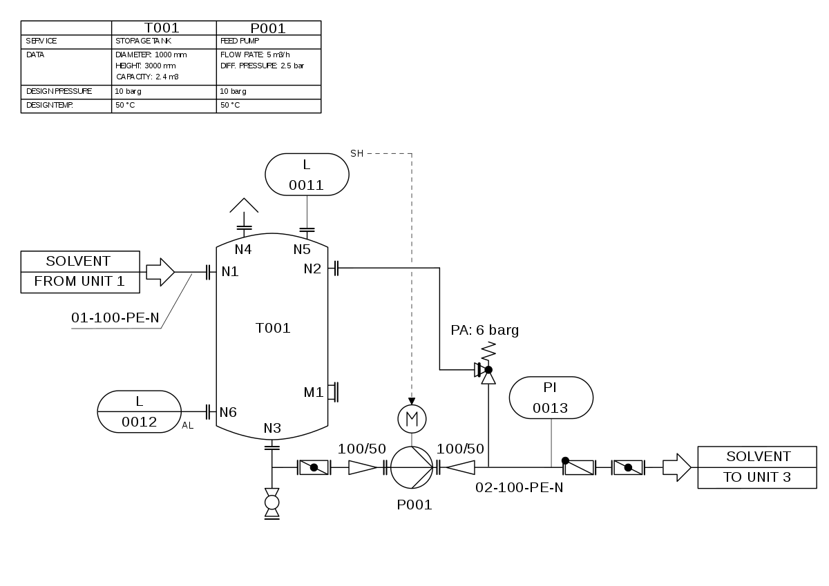
Legend & Symbols P&ID Bambang HN Tripatra, 1 Sept 14 Legend & Symbol Abbreviation Meaning BDV Indicator Flow Switch Non Intrusive Element Restricted Orifice Orifice Plate with Quick Change Fitting Low Pressure Process (300# ASME and lower) 1000 100 High Pressure Process (600# and higher) 00 0. A P&ID is a diagram that shows condensed information from multiple specialties This type of documents (the P&ID drawings) show, from the point of view of the process, different measures such as pressure, flow, level, etc and their respective control schemes in relation to the elements of the plant and its interconnection pipes. Click to print (Opens in new window) Click to share on Facebook (Opens in new window) Click to share on Twitter (Opens in new window) Click to share on LinkedIn (Opens in new window).
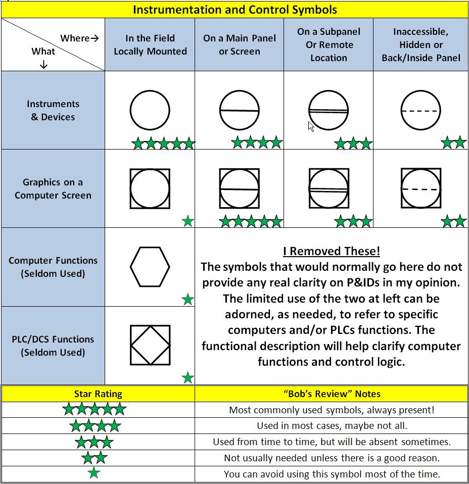
Piping and Instrumentation Diagrams—abbreviated P&IDs—are the schematics used in the field of instrumentation and control Field techs, engineers, and operators use P&ID symbols to better understand the process and how the instrumentation is interconnected. Academiaedu is a platform for academics to share research papers. Indicator (I), Record (R), Transmit (T), and so forth Example shows the story Referring to the Example P&ID diagram, FT 101 represents a fieldmounted flow transmitter connected via electrical signals (dotted line) to flow indicating controller FIC 101 located in a shared control/display device.
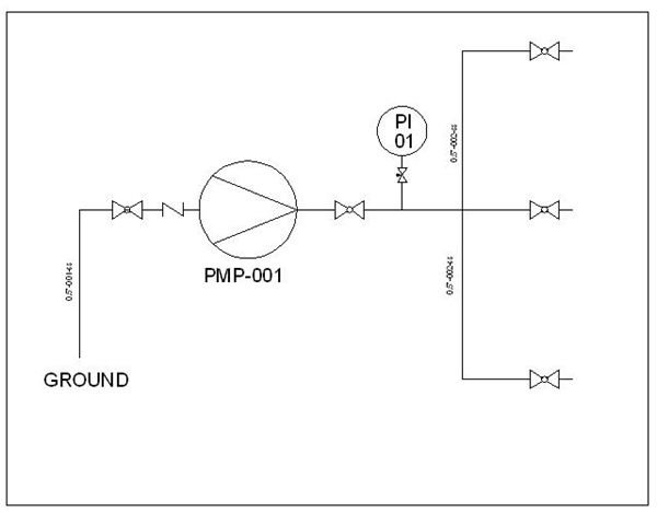
Pipe name code usually has info about pressure rating PRD setpoint is based on equipment/system MAWP at a defined temperature To monitor, control and for safety reasons you need to represent in the P&ID the pressure indicator, pressure transmitters, highpressure alarm, lowpressure switch and so on, only to name a few.

Instrumentation Today How To Read A P Id
Piping And Instrumentation Diagrams Tutorials I Learning Instrumentation And Control Engineering
Interpreting Piping And Instrumentation Diagrams Symbology Aiche
Pressure Indicator Pid Symbol のギャラリー

Piping And Instrumentation Diagrams Tutorials Ii Pressure Control Learning Instrumentation And Control Engineering

P Id Symbols And Notation Lucidchart

Chemical Engineering Basics P Id S T E M Share

Piping And Instrument Diagram P Id Standard Symbols Detailed Documentation Valve Switch

P Id Symbols And Notation Qa Qc Professionals
Pdhonline Com Courses E444 E444content Pdf

Standard P Id Symbols Legend
Piping And Instrumentation Symbols Instrumentation Tools

Basic Instrument Symbols Bmp 536 687 Chemical Engineering Piping And Instrumentation Diagram Process Engineering
Piping And Instrumentation Diagrams
P Id And Pfd Drawing Symbols And Legend List
4 2 Piping And Instrumentation Diagram Standard Notation Engineering Libretexts
Interpreting Piping And Instrumentation Diagrams Symbology Aiche
How To Read Piping And Instrumentation Diagram
Www Sawater Com Au Data Assets Pdf File 0019 Ts 112 Process And Instrument Diagrams Pdf
Learn How To Read P Id Drawings A Complete Guide

P Id Common Symbols How To Read A P Id Instrumentation And Control Engineering
Interpreting Piping And Instrumentation Diagrams Symbology Aiche

Piping Instrumentation Diagrams P Ids Punchlist Zero

Process Tech Oper Acad Board Mounted Isa Symbols
P Id And Pfd Drawing Symbols And Legend List Pfs Pefs

Piping Instrumentation Diagrams Guide Lucidchart
P Id In Autocad Creating Piping And Instrumentation Diagram Using Autocad Bright Hub Engineering
Http Lngacademy Weebly Com Uploads 2 0 8 5 Pid Symbols Pdf

Piping And Instrumentation Diagrams Tutorials Ii Pressure Control Learning Instrumentation And Control Engineering

P Id Symbols Complete List Pdf Projectmaterials
Sites Ntc Doe Gov Partners Tr Training textbooks 08 Engineering symbology prints and drawings 2 Mod 2 Engineering fluid diagrams and prints Pdf

P Id Symbol 3
Piping And Instrumentation Symbols Instrumentation Tools

363 Common P Id Symbols An Engineer S Library Vista Projects
Interpreting Piping And Instrumentation Diagrams Symbology Aiche

Instrumentation Symbols For P Id The Piping Engineering World
Http Www Sems1 Com Downloads Bsee Mar15 Sei Presentation2 Optional Pdf
1
4 2 Piping And Instrumentation Diagram Standard Notation Engineering Libretexts

Basics Of P Id Piping And Instrumentation Diagram Instrumentation And Control Engineering
Rb Eg Ue410 Preparation Of Pfd And Efd P Id
Emec130 P Id Symbol Primer

P Amp Id And Isa 5 1 The Basics Of Piping And Instrumentation Diagrams Visaya

Instrumentation Today How To Read A P Id

363 Common P Id Symbols An Engineer S Library Vista Projects

P Id Symbols Complete List Pdf Projectmaterials

P Ids Piping Instrumentation Diagrams And P Id Valve Symbol Library Assured Automation
Piping And Instrumentation Symbols Instrumentation Tools
P Id Symbols Complete List Pdf Projectmaterials

Pin On Tank

Instrumentation Diagrams Ispatguru

How To Read A P Id Diagram Industrial Automation Industrial Automation Plc Programming Scada Pid Control System

Pid Symbols Instrumentation Heat Exchanger
Common P Id Symbols Used In Developing Instrumentation Diagrams Learning Instrumentation And Control Engineering

Process Diagram Symbols Lowflow Valve Fractional Flow Control Valves Regulators
Q Tbn And9gcr Qvo0kilinp7vxn Yxett M7fmnmnm5rqqxvhzqnn08xy2pbm Usqp Cau
Http Www Sems1 Com Downloads Bsee Mar15 Sei Presentation2 Optional Pdf

What Is A P Id Diagram P Id Symbols Legend
Instrumentation Today How To Read A P Id
Instrument Abbreviations Used In Instrumentation Diagrams P Id Learning Instrumentation And Control Engineering

Typical P Id Arrangements And Symbols Enggcyclopedia
P Id Abbreviation
Http Www Hatelektrik Com Tr Belgeler P Id Symbol Pdf
Pdhonline Com Courses E444 E444content Pdf

Common P Id Symbols Used In Developing Instrumentation Diagrams Learning Instrumentation And Control Engineering
Piping And Instrumentation Symbols Instrumentation Tools

What Is A Legend Chart Types Of Legend Diagrams
Piping And Instrumentation Diagram P Id Symbols Distributed Control Systems Dcs Instrumentation Forum

What Is A P Id Diagram P Id Symbols Legend

Piping And Instrumentation Diagram P Id Symbols Distributed Control Systems Dcs Instrumentation Forum
Piping And Instrumentation Diagram Wikipedia
P Id Symbol Diagram Basics 3 3 Functional Identification And Naming Conventions
Interpreting Piping And Instrumentation Diagrams Symbology Aiche
Lire Et Creer Des Schemas De Procedes Moulay El Hassane El Moukrie Ingenieur Procedes Industriels Et Genie Chimique A La Recherche D Opportunites
P Id Common Symbols How To Read A P Id

What Is A P Id Beginner S Guide Edrawmax Online
1 3 Piping And Instrumentation Diagram P Id Diagrams For Understanding Chemical Processes Informit
P Id Symbols Complete List Pdf Projectmaterials
Q Tbn And9gcqwh7qhl47fr5pzbzdwvfpraiqzyim T0671lf0fpxwcg60 H3g Usqp Cau
Rb Eg Ue410 Preparation Of Pfd And Efd P Id

Visio Sample P Id Vsd
P Ids Piping Instrumentation Diagrams And P Id Valve Symbol Library Assured Automation

P Id Diagram Of The Laboratory Scale Sorption Apparatus G Gas Washing Download Scientific Diagram

Typical P Id Arrangement For Storage Tanks Enggcyclopedia

P Ids Piping Instrumentation Diagrams And P Id Valve Symbol Library Assured Automation
Q Tbn And9gcsncivnt45b2uxqwi55vjipgzxzfi Beln4s3pwiof5j8p Kb5v Usqp Cau

P Id Symbols With Letters Piping And Instrumentation Diagram Diagram Abbreviations

1 St Separation System With The Esd System 19 Rectangular With Dot Download Scientific Diagram

Instrument Lines Gallery

What Is A P Id Diagram P Id Symbols Legend
What Is A P Id Beginner S Guide Edrawmax Online
Nikolay Bozov Industrial Automation And Control

363 Common P Id Symbols An Engineer S Library Vista Projects

Function Symbols Learn Automation Electrical And Instrumentation
Piping And Instrumentation Diagrams

60a3 R1 Instrumentation Symbols And Identification Pdf
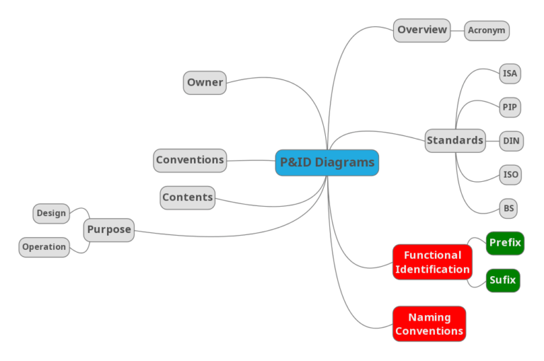
P Id Symbol Diagram Basics 3 3 Functional Identification And Naming Conventions

10 Idees De P Id Cablage Electrique Maison Chauffage Climatisation Cablage Electrique
Www Sawater Com Au Data Assets Pdf File 0019 Ts 112 Process And Instrument Diagrams Pdf
Autoquiz P Id Determination For Temperature And Pressure Sensors
P Id Symbols Complete List Pdf Projectmaterials
What Is A P Id Beginner S Guide Edrawmax Online
Autocad Plant 3d Spec Driven P Ids Imaginit Manufacturing Solutions Blog
P Id Symbols Complete List Pdf Projectmaterials
Sites Ntc Doe Gov Partners Tr Training textbooks 08 Engineering symbology prints and drawings 2 Mod 2 Engineering fluid diagrams and prints Pdf


