
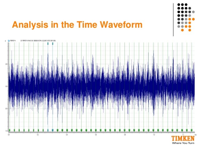
Time Waveform Vibration Analysis
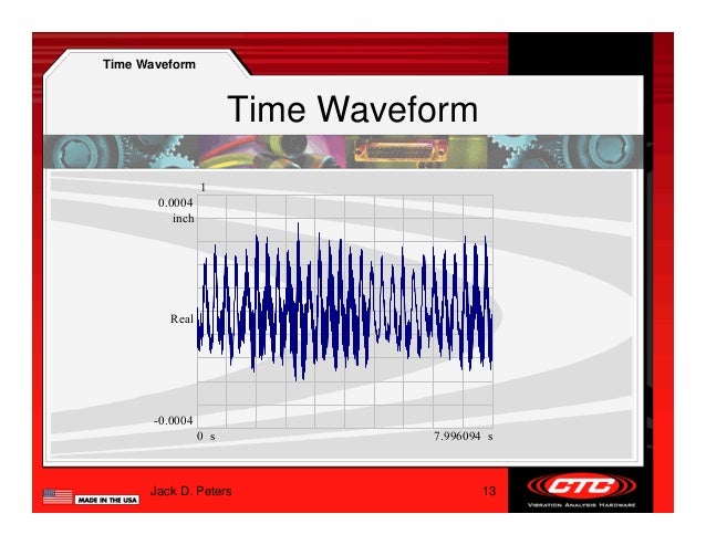
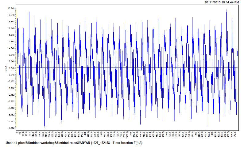
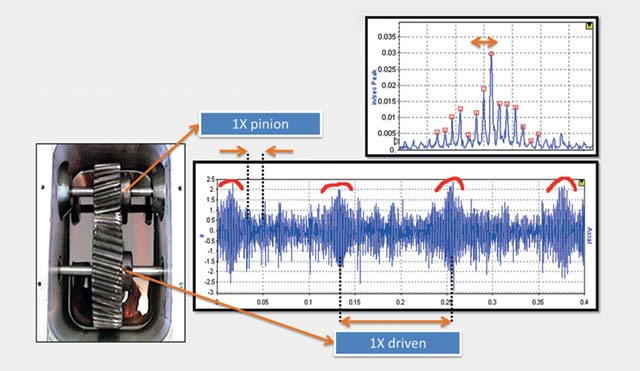
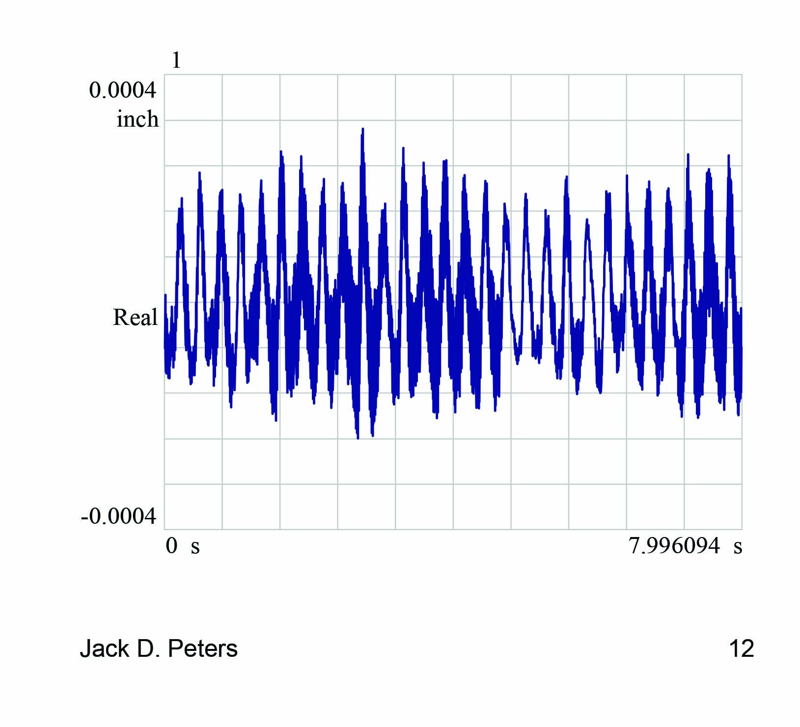
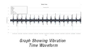
The vibration data is accomplished with actual waveform compensation, where a time waveform is recorded at low speed instead of just a vector An example of a compensated time wave form is shown in Figure 6.
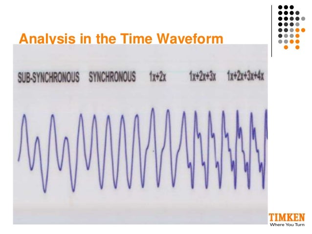
Time waveform vibration analysis. 1 Waveform setup fundamentals 2 FFT Setup fundamentals 3 Knowledge to avoid common pitfalls in setups About the Presenter Dennis is the Lead Technician for Wearcheck Reliability Solutions with 18 years of condition monitoring experience Qualifications include NDip Mechanical Engineering, Vibration ISO CAT IV certification and ODS and Modal. Timewaveform analysis can enhance machine vibration analysis It should not be considered a primary tool but rather as a tool to provide additional insights It can be useful for lowspeed applications because it reveals the way the machine is moving Timewaveform analysis is frequently used for analyzing gears, for example. •When reduced to it’s most basic concept, Vibration Analysis time deciding where to start their analysis • The vast majority of the time, the largest amplitude will be the machine problem • On rare occasions, the highest amplitude will not be in • Visualize the waveform motion that generates each.
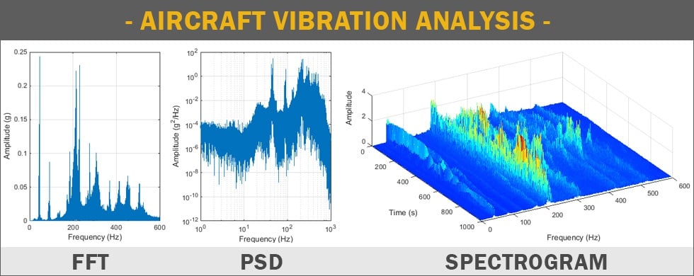
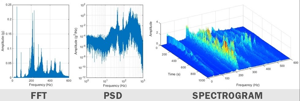
Time waveforms display a short time sample of the raw vibration Though typically not as useful as other analysis formats, time waveform analysis can provide clues to machine condition that are not always evident in the frequency spectrum and, when available, should be used as part of your analysis program. The right column of the Basic Processes diagram shows that the time waveform can be converted to a frequency spectrum in order to show the analyst where the vibration energy is coming from Frequency analysis is the essence of vibration analysis and enables the satisfactory resolution of most machine problems. Time waveform analysis can present, in a static picture, amplitude variations and changes in frequencies that the FFT cannot display without using multiple (dynamic) graphics Further, a waveform graphically presents accurate peak vibration amplitudes representing defect severity.
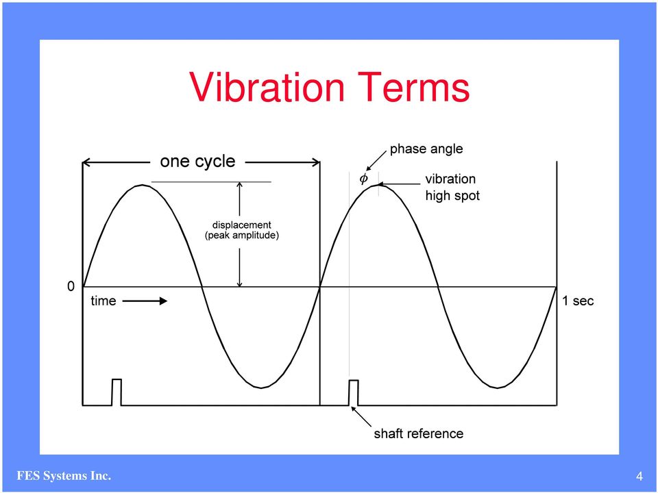
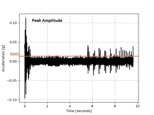
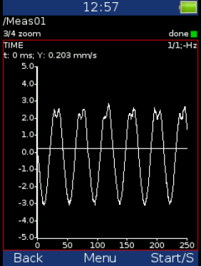
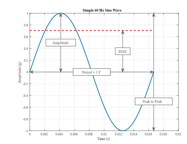
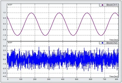
The default set up is “Low Range” = 300 Hz “High Range” – 8000 Hz and Demod = 600 Hz My Time waveform shows 5 seconds of data My Low range FFT’s goes out to 12X and High range goes to 300X In this example my RPM is set at 1705 If T= LOR/Fmax then it appears to be using the “Low Range” setting of 300 Hz and giving me 5 seconds of data. Simple Vibration Analysis in the Time Domain When analyzing vibration data in the time domain (acceleration/vibration amplitude plotted against time) we’re limited to a few parameters in quantifying the strength of a vibration profile amplitude, peaktopeak value, and RMS A simple sine wave is shown below with these parameters identified. Quickly perform a vibration analysis and evaluate alignment with Fluke's vibration sensors testing and laser shaft alignment equipment and systems Time waveform 1 Spectral analysis 1 Overall vibration 3 Highfrequency bearing measurement 3.
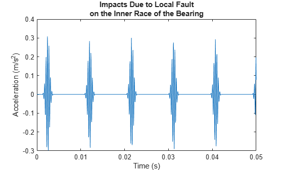
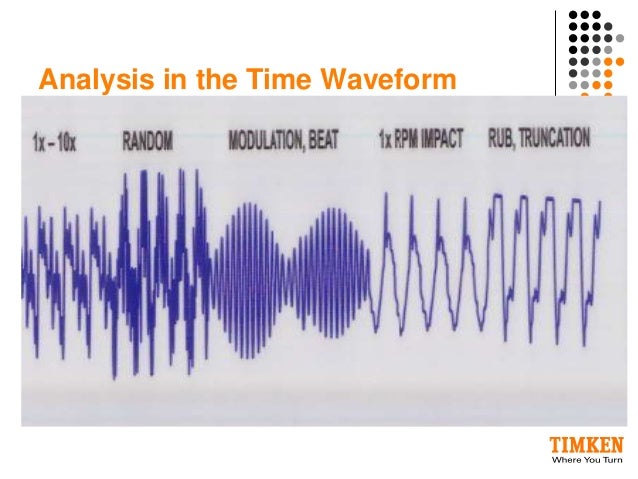
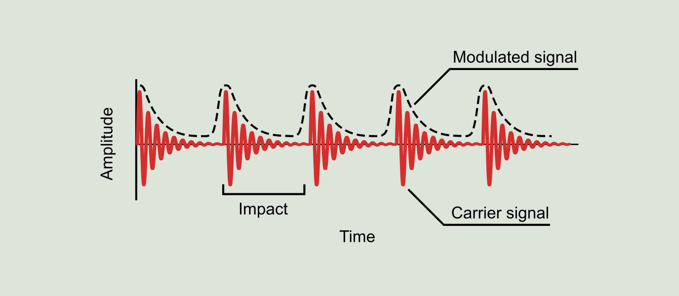
The Time Waveform Analysis (TWA) class is three days of instruction in the use of TWA to correctly diagnose machine faults that are difficult or impossible to detect and diagnose using FFT spectrum analysis Attendees should be experienced in the use of data collection, FFT analysis, vibration instrumentation and software. I have inherited a database with an AP set 3000Hz/6400L/3Av and STW (special time waveform is ticked) this AP is used extensively throughout the database A particular issue I have is limited shaft revs are being captured 4 only on a 1490 rpm shaft By my calculations data collection time with just 1 average should capture at least 11 or 12 revs. Time waveforms contain key details that help you to solve rolling element bearing defects, gear tooth defects, pump flow problems, and basically every other failure mode that involves impacts, rubs, turbulence, or vibration that varies from cycle to cycle (eg modulation and beating) Time waveform analysis helps you to detect faults that you could easily miss with spectrum analysis, and it enables you to understand the exact nature and severity of the fault condition.
Time Waveform and FFT Spectrum Analysis 03/08/18 The below video is a 5 minute segment of a 30 minute long presentation given by Adam Smith, CMRT and Jacob Bell of HECO PSG at the 17 Reliability, Process, and Maintenance (RPM) Symposium This presentation discusses the basics of vibration analysis as a predictive maintenance tool. Auto correlation Auto correlation is a time domain analysis, computed from the peak value time waveform that is useful for determining the periodicity or repeating patterns of a vibration signal The auto correlated waveform can be presented in a circular format, which makes interpretation of the data much more straightforward. Visualize the timesynchronized signals for a single rotation.
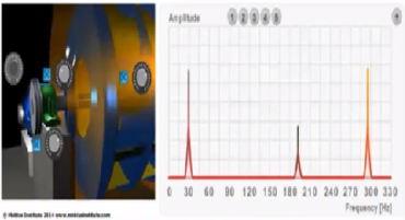
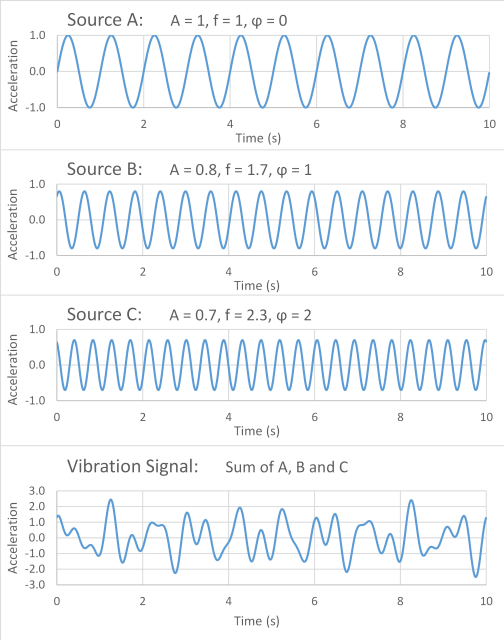
VIBRATION waveform as shown in the time drawing on the left side This is the summation of all the vibration present at that location Spectrum analysis enables us to untangle this complex waveform and make a representation of its original components on a diagram showing frequency on the Xaxis and amplitude vertically. Time waveforms can help you rule in or out certain fault conditions Impacts, rubs, and looseness can be seen clearly in the waveform Diagnosis of misalignment, imbalance, and bearings faults can be aided by time waveform data Time waveform measurements are essential when studying low speed machines and gearboxes. 1 Waveform setup fundamentals 2 FFT Setup fundamentals 3 Knowledge to avoid common pitfalls in setups About the Presenter Dennis is the Lead Technician for Wearcheck Reliability Solutions with 18 years of condition monitoring experience Qualifications include NDip Mechanical Engineering, Vibration ISO CAT IV certification and ODS and Modal.
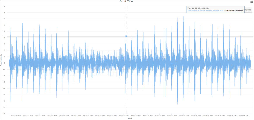
Time waveform in vibration measurement technology is basically known as “raw signal” as it represents a real information from the machine about forces being generated As a first step of measurement, all vibration analyzer captures time wave form and then process it to bring various characteristic value. The time waveform is a record of exactly what happened from moment to moment as the shaft turns, the gears mesh, the vanes pass through fluid, and the rolling elements roll around the bearing Each minute change that results from impacts, rubs, scrapes, rattles, surges, and so much more is recorded in the time waveform and then summarized in the spectrum. Time 1 1 V Peak 0 Magnitude 0 Hz 100 Hz Pwr Spec 1 dX ms dY mV X ms Y mV X55 Hz Y mV The time wave has not changed The Peak value is expressed from zero to the largest positive or negative peak amplitude The peak value is measured in the time waveform Peak = 1 V.
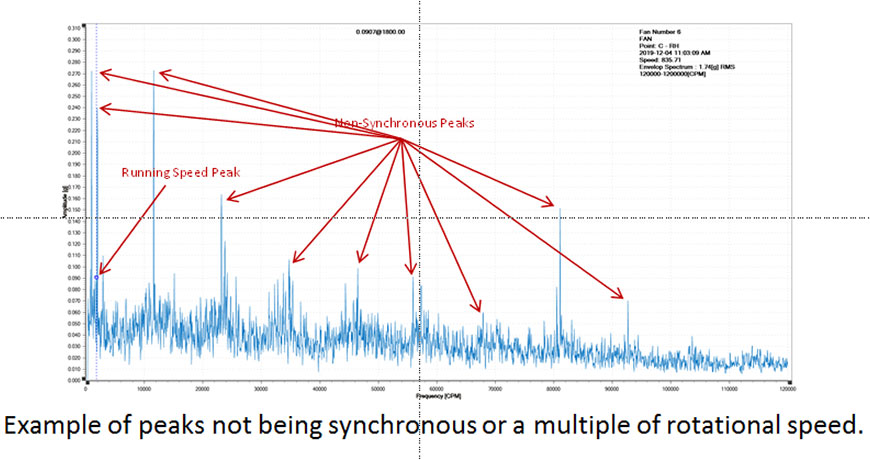
Vibration analysis is a process that monitors vibration levels and investigates the patterns in vibration signals It is commonly conducted both on the time waveforms of the vibration signal directly, as well as on the frequency spectrum, which is obtained by applying Fourier Transform on the time waveform. This year, Technical Associates will continue to offer Industrial Vibration Analysis Seminars (both public and inplant) with Analyst Certification Testing TIME WAVEFORM ISO CATEGORY I (Entry) ISO CATEGORY II (Analysis I) ISO CATEGORY III (Analysis II) ISO CATEGORY IV, Part 1 (Analysis III). This creates a centrifugal force, leading to high vibration amplitudes at frequencies equal to 1xRPM (1x rotational speed) in spectral data, with a sinusoidal waveform in the time domain On rigidly mounted machines, amplitudes will typically be highest in the horizontal direction rather than the vertical direction, although raised amplitudes can also exist axially on overhung rotors.
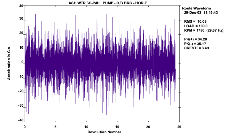
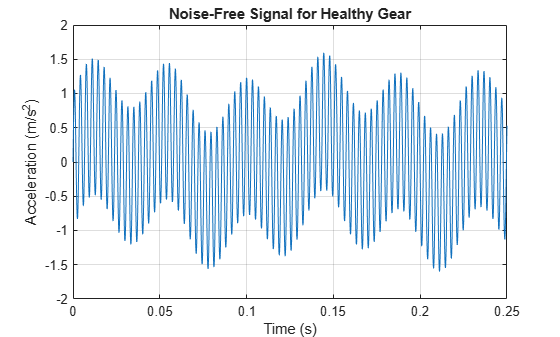
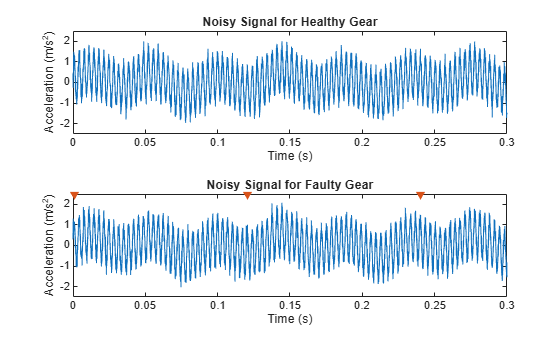
•When reduced to it’s most basic concept, Vibration Analysis time deciding where to start their analysis • The vast majority of the time, the largest amplitude will be the machine problem • On rare occasions, the highest amplitude will not be in • Visualize the waveform motion that generates each. The time domain analysis, on chronologically recorded vibration waveforms, reveals when and how severe the abnormal vibration events occur, by extracting and studying parameters including but not limited to rootmeansquare (RMS), standard deviation, peak amplitude, kurtosis, crest factor, skewness and many others. TaGear = tsa (vFaultNoisy,fs,tPulseOut, 'NumRotations' ,10);.
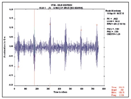
Time 1 1 V Peak 0 Magnitude 0 Hz 100 Hz Pwr Spec 1 dX ms dY mV X ms Y mV The time wave has not X55 Hz Y mV changed The Peak value is expressed from zero to the peak amplitude The spectrum value uses the suffix “Peak” to denote this. Any time the vibration might include periodic impacts, beats, rubs, modulation, transients and random bursts of energy, time waveform analysis data is the best to use Fault conditions ideal for using time waveform for diagnoses include Rolling element bearings;. Time waveform analysis Figure 6 A sample time waveform from a gearbox with a broken tooth It is very easy to collect time waveform measurements, and you should use these measurements to help confirm the diagnosis Time waveforms can help you rule in or out certain fault conditions.
Vibration means the state of an object moving repetitively back/forward, right/ left or up/down and is generally expressed by Frequency, Displacement, Velocity, and Acceleration These 4 elements are generally denoted as F, D,V,A This is illustrated simply as a spring and mass. Timewaveform analysis can enhance vibration analysis It should not be considered a primary tool but rather as a tool to provide additional insights It can be useful for lowspeed applications because it reveals the way the machine is moving Timewaveform analysis is frequently used for analyzing gears, for example. When the spectrum is not enough to make a decision about what’s going on inside the machine, it’s a good idea to go for waveform, time waveform analysis provides details not found in the spectrum.
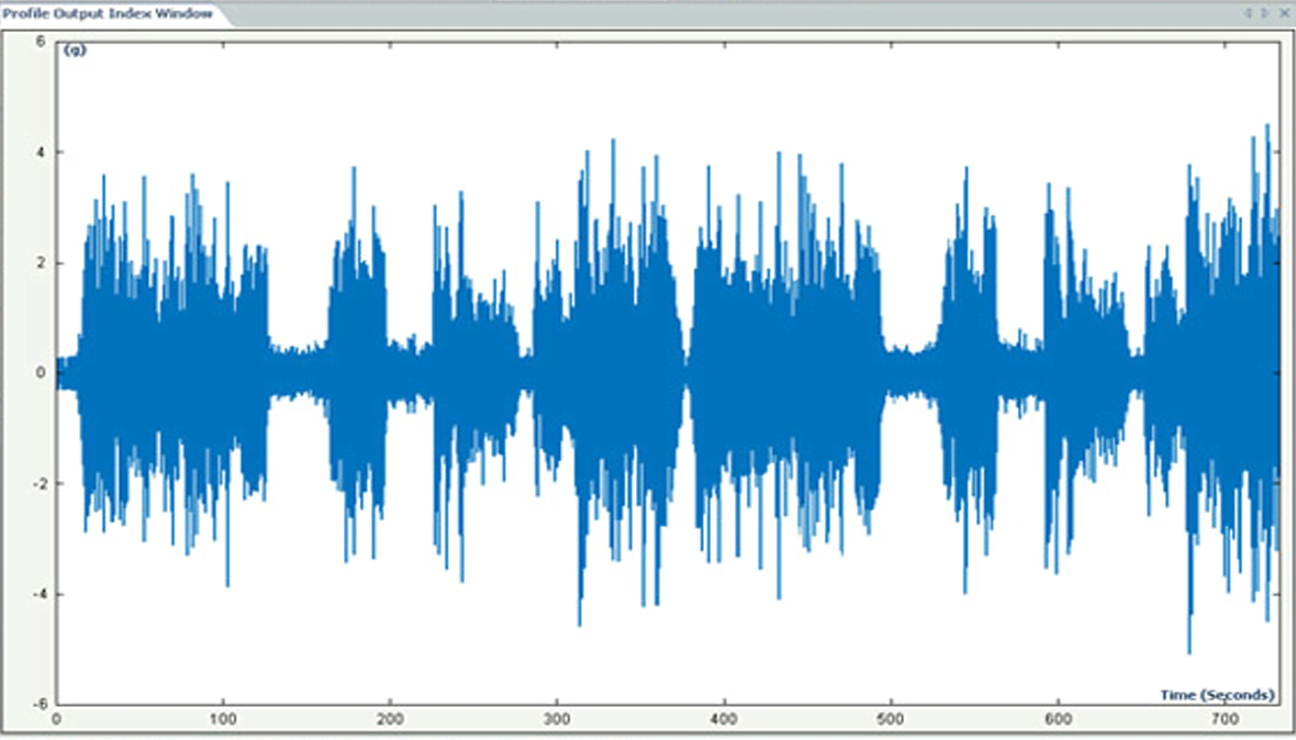
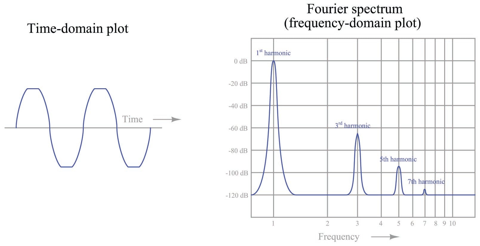
Time waveform analysis means looking at the raw plot of acceleration against time, as shown in the initial example Because this is often too complex to extract any useful information, people often skip straight past it to the spectrum analysis. Vibration analysts often look at a time waveform and assume it is a valid representation of the component being monitored Analysts may forget the time waveform is a digital representation of the raw analog signal Due to it being a digital representation, the time waveform is limited by the signal processing parameters the analyst defines. The representation of a vibration signal in the time domain is a “wave form,” and this is what one would see if the signal were displayed on an oscilloscope If the waveform is subjected to a spectrum analysis, the result is a plot of frequency vs amplitude, called a spectrum, and the spectrum is in the frequency domain.
The basics of vibration analysis include identifying the predominant frequency at which the vibration occurs and then determining what is the forcing function that is the cause Reduction of the forcing function will many times reduce the amplitude of the component that is the concern For this level of analysis the most common display. Prior to the commercial availability of spectral analysers, almost all vibration analysis was performed in the time domain By studying the time domain waveform using equipment such as oscilloscopes, oscillographs, or ‘vibrographs’, it was often possible to detect changes in the vibration signature caused by faults. Vibration signal analysis has been widely used in the fault detection of rotation machinery The vibration signal of a gearbox carries the signature of the fault in the gears, and early fault.
Vibration analysis is a process that monitors vibration levels and investigates the patterns in vibration signals It is commonly conducted both on the time waveforms of the vibration signal directly, as well as on the frequency spectrum, which is obtained by applying Fourier Transform on the time waveform. Time waveform analysis is the ideal tool when diagnosing a range of fault conditions, including rolling element bearing faults, faults associated with gears, cavitation, rubs, looseness and more any time the vibration may include impacts, modulation, beats, rubs, transients, and random bursts of energy, time waveform analysis is the best data to view Time waveform analysis is so useful because the waveform is a recording of exactly what happened in the machine from one moment to the next. Imbalance Imbalance occurs when the centre of mass differs from the centre of rotation This creates a centrifugal force, leading to high vibration amplitudes at frequencies equal to 1xRPM (1x rotational speed) in spectral data, with a sinusoidal waveform in the time domain.
These questions continue to be some of the most commonly asked in the vibration analysis community and not just from individuals who are new to the field There are many experienced analysts who do not use the time waveform as part of their day to day analysis and there are those who do not even collect it as part of their PdM program Some analysts only consider collecting the waveform as part of “advanced troubleshooting”. The analysis of time waveform data is not a new technique In the early days of vibration analysis time waveform data was viewed on oscilloscopes and frequency components calculated by hand The relationship between frequency and time is as follows f = 1/p. Overview This threeday seminar provides indepth coverage of Time Waveforms and how they can be used to detect a wide variety of faults, plus how they can be used to assess the severity of such faults While the focus of the class is on vibration time waveforms, it likewise clearly shows how a different approach should be taken when acquiring and evaluating High Frequency Envelope (HFE) waveforms versus classic vibration waveforms (including a difference in setup parameters for HFE waveforms).
Timewaveform analysis can enhance machine vibration analysis It should not be considered a primary tool but rather as a tool to provide additional insights It can be useful for lowspeed applications because it reveals the way the machine is moving Timewaveform analysis is frequently used for analyzing gears, for example. Specify timesynchronized pulses for the gear Calculate the timesynchronous average for 10 rotations of the gear tPulseOut = 01/fGearmax (t);. The representation of a vibration signal in the time domain is a “wave form”, and this is what you would see if the signal were displayed on an oscilloscope If the waveform is subjected to a spectrum analysis, the result is a plot of frequency vs amplitude, called a spectrum, and the spectrum is in the frequency domain.
Time Waveform Analysis A uniquely effective threeday course An essential skill for experienced vibration analysts Time waveform analysis is a powerful condition monitoring tool yet it is often misunderstood and as a result, underutilized Even the most experienced vibration analysts will learn new techniques and have the opportunity to. Vibration means the state of an object moving repetitively back/forward, right/ left or up/down and is generally expressed by Frequency, Displacement, Velocity, and Acceleration These 4 elements are generally denoted as F, D,V,A This is illustrated simply as a spring and mass. Time Waveform and FFT Spectrum Analysis 03/08/18 The below video is a 5 minute segment of a 30 minute long presentation given by Adam Smith, CMRT and Jacob Bell of HECO PSG at the 17 Reliability, Process, and Maintenance (RPM) Symposium This presentation discusses the basics of vibration analysis as a predictive maintenance tool.
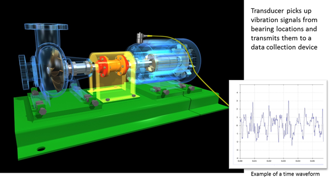
Facts About Vibration Vibration is movement relative to a reference position, such as the center line of a shaft on rotating equipment Vibration is a result of an excitation force or forcing function and may be either random or periodic Vibration analysis can often pinpoint a failing element of a rotating machine in time to avoid catastrophic failure and costly replacement of machinery as well as lengthy production interruptions Each machine fault generates a specific vibration pattern. Time waveform analysis helps you to detect faults that you could easily miss with spectrum analysis, and it enables you to understand the exact nature and severity of the fault condition. A vibration analyst can use this information usually in the form of a Time Waveform and an FFT Spectrum Analysis to detect a variety of machine faults Time Waveform When the displacement data is combined with time data, the result is a Time Waveform (or time domain) plot that shows the relationship between amplitude and time.
Time waveform analysis means looking at the raw plot of acceleration against time, as shown in the initial example Because this is often too complex to extract any useful information, people often skip straight past it to the spectrum analysis. Time Waveform Replication TWR allows for measuring your own time vibration data and playing it back on a shaker Any arbitrary number of time profiles can be run on a defined schedule, duplicating long waveforms as precisely as they were recorded. Switching between time and frequency is a common tool used for analysis Because the frequency spectrum is derived from the data in the time domain, the relationship between time and frequency is very important Units of acceleration, velocity, and displacement are typical Additional terms such as peakpeak, peak, and rms are often used.
Vibration analysts often look at a time waveform and assume it is a valid representation of the component being monitored Analysts may forget the time waveform is a digital representation of the raw analog signal Due to it being a digital representation, the time waveform is limited by the signal processing parameters the analyst defines. Time waveforms display a short time sample of the raw vibration Though typically not as useful as other analysis formats, time waveform analysis can provide clues to machine condition that are not always evident in the frequency spectrum and, when available, should be used as part of your analysis program. Time waveform analysis is the ideal tool when diagnosing a range of fault conditions, including rolling element bearing faults, faults associated with gears, cavitation, rubs, looseness and more any time the vibration may include impacts, modulation, beats, rubs, transients, and random bursts of energy, time waveform analysis is the best data to view.
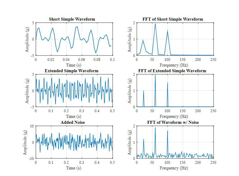
Simple Analysis in the Time Domain When analyzing vibration data in the time domain (amplitude plotted against time), we’re limited to a few parameters in quantifying the strength of a vibration profile amplitude, peaktopeak value, and RMS Figure 3 shows a simple sine wave with these parameters identified.
Fieldpaq Ii Vibration Tester
Vibration Analysis Of Rotating Machinery Matlab Simulink Mathworks Benelux
Vibration Analysis Services Fes Systems Inc 1 Pdf Free Download
Time Waveform Vibration Analysis のギャラリー

Imbalance Misalignment Looseness Know The Difference Hansford Sensors

How Are Fast Fourier Transforms Used In Vibration Analysis
Time Waveform Replication Bruel Kjaer
Vibration Analysis Fft Psd And Spectrogram Basics Free Download
01 Beginning Vibration Analysis
Time Waveform Analysis Cbm Connect
Q Tbn And9gcq3nma8hkfkqglzdq Oz0tvg30cglxy4d 4kaxhzbbhzzp3ddd8 Usqp Cau
What Is Vibration Analysis And What Is It Used For Twi

What Is Vibration Analysis Time Waveform And Fft Spectrum Analysis
Textbook Iso Category Iv Part 1 Vibration Analysis Iii

Get Better Insights From Your Vibration Data
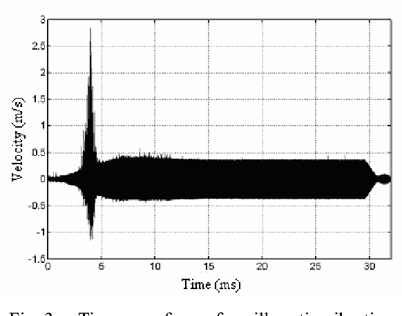
Figure 3 From Joint Time Frequency Analysis Of Capillary Tip Vibration In Thermosonic Wire Bonding Semantic Scholar
Www Emerson Com Documents Automation White Paper High Frequency Vibration Analysis Ams En Pdf
Vibration Study And Analysis Service Carelabz Com

What Is Vibration Analysis Time Waveform And Spectrum Fft Analysis Youtube

Vibration Analysis Know How Quick Intro To Vibration Analysis Youtube

Time Wavefrom Signal Processing

Vibration Analysis Explained Reliable Plant
Engineering Com Vibration Analysis Take A Virtual Look Inside Your Operating Machinery

Vibration Analysis Services Fes Systems Inc 1 Pdf Free Download

Vibration Analysis Of Rotating Machinery Using Time Frequency Analysis And Wavelet Techniques Sciencedirect

Vibration Analyzer Wireless Digivibe M30 From Erbessd
Vibration Analysis Time Waveform Analysis By Mobius Institute Youtube
Vibration Physics Introduction To Machine Vibration Measurement Automation Textbook

Vibration Analysis Explained Reliable Plant
Sspn Reliabilityedge Pvt Ltd Omkar Group Company
Ten Things Vibration Analysts Should Do But Often Don T Cmms Maintworld

Vibration Analysis ช ไทยว ทยบร การ
Www Unitechinc Com Pdf Introductiontotimewaveformanalysis Pdf
What Is Vibration Analysis And What Is It Used For Twi

Time Frequency Analysis Method Of Bearing Fault Diagnosis Based On The Generalized S Transformation Jve Journals

How Does Vibration Analysis Work

Vibration Analysis Doane Reliability Solutions

Time Domain Waveform Of Iscs Of Vibration Signal Of Roller Bearing With Download Scientific Diagram

The 10 Most Important Vibration Analysis Tips You Need To Know Erbessd
Vibration Analysis

Iso Category Iii Analysis Ii

Engineering

Seminars Time Waveform Analysis On Rotating Machinery
Vsc Screw Compressor Vibration Analysis Case Study Vsc

Time Waveform Of Vibration And Current Signals Download Scientific Diagram
Adash 300 Va3pro 3 Channel Vibration Analyzer Data Collector
Vibration Diagnostics

Time Domain Waveform Of The Vibration Signal At Inner Ring Fault Download Scientific Diagram
Www Unitechinc Com Pdf Introductiontotimewaveformanalysis Pdf
Q Tbn And9gcqxjxgz1qbbpmoc Fdbobwyiqcmvnkfapwppdj9a Xerawiaiwd Usqp Cau

The Rolling Bearing Fault Feature Extraction Based On The Lmd And Envelope Demodulation
Vibration Analysis
Q Tbn And9gctx1elxzpjy8nfnqwlyzcdqpshf3j Lft8dykbwtnwl0y7z7q Usqp Cau
The Ultimate Guide To Vibration Analysis
What Is Vibration Analysis

Cat I Vibration Analysis Vcat I Rms Ltd
Vibration Analysis Of Rotating Machinery Matlab Simulink Mathworks Benelux
Vibration Analysis

Engineering Com Vibration Analysis Take A Virtual Look Inside Your Operating Machinery

Wall Charts

Vibration Analysis Doane Reliability Solutions

Vibration Analysis Basics Oneprod

Vp5 Vibration Data Collector

A The Time Waveform Of The Original Vibration Signal Of Record 176 De Download Scientific Diagram
Www Unitechinc Com Pdf Introductiontotimewaveformanalysis Pdf
Vibration Analysis

Services Industrial Diagnostic Systems Services Llc

Vibration Analysis How The Fft Is Derived Time Waveform To Spectrum Youtube
Evaluating Using Data Vru

Vibration Data Collector Signal Analysis Crystal Instruments Leading Innovation In Vibration Testing Condition Monitoring And Data Acquisition

Vibration Analysis Basics Oneprod

Machine Vibration Analysis
Time Waveform Analysis Cbm Connect

The New Generation Of Online Vibration Analysis Reliabilityweb A Culture Of Reliability
Www Emerson Com Documents Automation White Paper High Frequency Vibration Analysis Ams En Pdf

Vibration Analysis Basics Oneprod

Vibration Signal Of Rolling Element Fault Bearing After Tmf Analysis Download Scientific Diagram
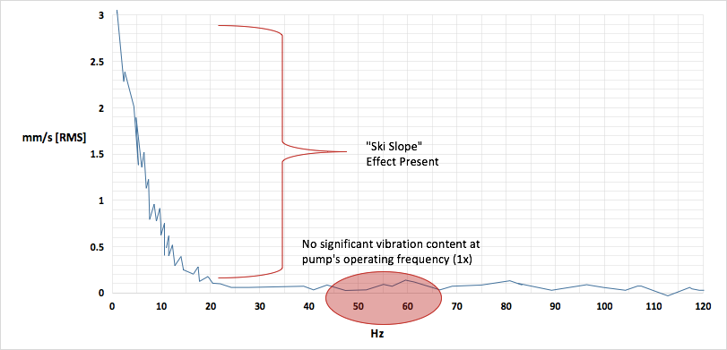
Experiencing Lng Pump Vibration Time Waveform Instability Or A Ski Slope In The Vibration Spectrum Try This Easy Fix Niche Cryogenic Solutions

Vibration Analysis Monitoring Auricle Vibration Services Private Limited
Vibration Analysis And Signal Processing In Labview Ni
Vibration Analysis Vibration Monitoring Dynapar

Creating A Monitoring Program For Determining Dynamic Modulus And Other Ore Properties From Blasting Operations In An Underground Mine

Time Waveform Analysis Course Rms Ltd
Q Tbn And9gcqahcb1aoum Hv342xfso9bco7wwsejbdj2rziocngiccxhr5be Usqp Cau
Vibration Analysis Of Rotating Machinery Matlab Simulink Mathworks Benelux

Time Waveform Analysis And Statistical Comparison Amp Maintenance Forums
Www Unitechinc Com Pdf Introductiontotimewaveformanalysis Pdf
Make Sure To Include These 8 Steps To Your Vibration Analysis Process Ludeca
Time Waveform Cbm Connect

Pdf Vibration Analysis And Diagnostic Guide

Vibration Analysis Explained Reliable Plant

Vibration Monitoring Analysis Ppt Video Online Download
Demodulation Or Envelope Analysis Power Mi
The Ultimate Guide To Vibration Analysis
Vibration Measurement Time Waveform Sander Mechanical Service

Vibration Measurement Techniques By Gaxcesensor Issuu

How Are Fast Fourier Transforms Used In Vibration Analysis

Time Waveform Analysis Amplitude Modulation

Vib Peakvue As Part Of Bearing Mechanical Spectral Density

Vibration Analysis Explained Reliable Plant
Vibration Analysis Vibration Monitoring Dynapar
Www Unitechinc Com Pdf Introductiontotimewaveformanalysis Pdf
Basics Of Structural Vibration Testing And Analysis Crystal Instruments Leading Innovation In Vibration Testing Condition Monitoring And Data Acquisition
Vibration Measurements Vibration Analysis Basics
The Vibration Analyst Checklist Do You Pass Maintenance And Engineering


